Operation instruction of parallelism measurement
1. Set-up
AutoMAT auto-collimator
Pentagon prism
Bridge plate with mirror
Laser attachment (LFxx)
1.1 Set the baseline and the measuring line
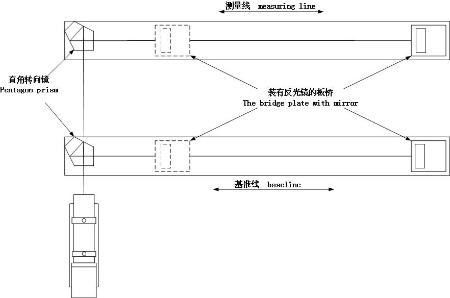
Fig1: General view of parallelism measurement
1.2 Installing auto-collimator
Auto-collimator should be placed on a solid base, and connecting cables, start the measurement software on a computer.
1.3 Auto-collimator adjustment
a) Put the measurement bridge plate in the baseline near the pentagon prism, start the measurement with auto-collimator software.
b) Put the laser attachment(LF1 or LF2) at the front of the Auto-collimator’s objective tube,the laser attachment emits a laser beam,let the laser beam shoot at the middle of the mirror. Adjust the mirror to make sure the laser beam is reflected back to the emitting point . Take down the laser attachment. Gently knock the bridge plate to adjust the mirror angle of horizontal deflection,and use the pitching knob to adjust the pitching axis, making the measurement value of image close to the origin.
c) Rotate the mirror in X axis by ±1000", check the deviation of the Y axis, which is kept below 10" at least. If not, turn the and check the deviation again until it meet the requirement.
1.4 Auto-collimator coaxial adjustment
a) Put the measurement bridge plate in the baseline near the pentagon prism, adjust the image near the origin
b) Move the mirror to the end of baseline, rotate the horizontal and vertical adjustment knob of auto-collimator making the position value of the image close to the origin;
c) Put the pentagon prism in front of the measuring line, let the bridge placed near the pentagon prism in measuring line. Put the laser attachment at the front of the objective tube, let the laser beam shoot at the middle of the mirror. Adjust the mirror to make sure the laser beam is reflected by the mirror to the measuring head. Take down the laser attachment, gently knock the bridge plate to adjust the measurement value of X Axis close to the origin.
2. Data Measurement
It is recommended to start up the equipment for about 30 minutes before starting measurement, and it is beneficially for optimal measuring accuracy.
2.1 Baseline measurement
a) Put the pentagon prism in front of the baseline and move the mirror near the pentagon prism, Click the button “Save (F9)” to save the current measured value.
b) Move the mirror to the next point, click the button “Save (F9)” to save the current measured value.
c) Repeat,until the measurement of baseline finished.
2.2 Measuring line measurement
a) Put the pentagon prism in front of the measuring line and move the mirror near the pentagon prism, Click the button “Save (F9)” to save the current measured value.
b) Move the mirror to the next point, Click the button “Save (F9)” to save the current measured value.
c) Repeat, until the measurement of baseline finished.
2.3 Save Testing Data
Click the button “Run (F1)” after the measurement stopping, click F9 again the operation dialog of the saved data will appear.
Attention: The position of auto-collimator can’t be moved during the measurement
3. Data processing
3.1 Import data、setting parameters
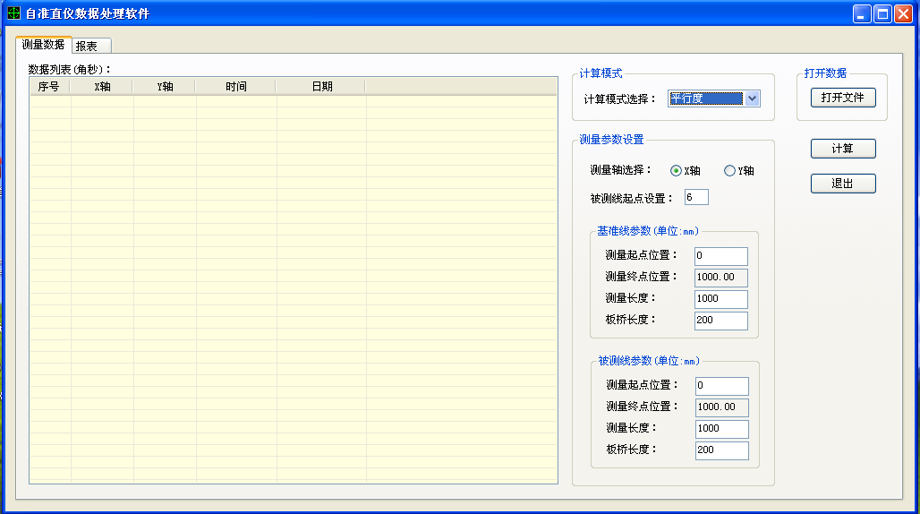
Fig2: parallelism calculation software
a) Close the measurement software after the measurement is finished, Open the software of parallelism calculation ,as is shown above.
b) Click the button of the “Open file”, the open file dialog will appear, find out the file saved before, The data will be displayed in the data list.
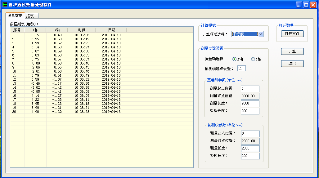
Fig3: Import data
l Set parameters
l Calculation mode
l Choose the parallelism
a) Chosen of the Measurement axis
b) Starting point
c) Baseline parameters、measuring line parameters
a) Choose the axis of the parallelism Calculation
b) According to the serial number of the list, as is shown above, the first ten values is the baseline data, the last ten values is the measuring line data; so, the starting point is 11.
c) Set the starting point of measurement, measuring length and bridge length, the endpoint is calculated by the software according to start point; the software will check the measuring length and the endpoint.
3.2 Calculate parallelism result
Click the button of “Calculation”, the software will use the data and parameter to compute linearity, and change to the report tag.
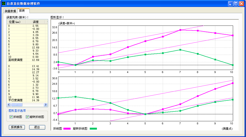
Fig4: Linearity
3.3 Report
After calculating, the report can be save and print.
a) Setting up headers
Click the button of “Report Operations”, the dialog below will appear.
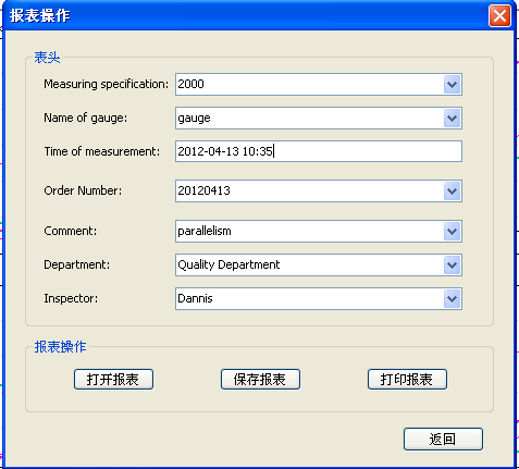
Fig5: Report header
b) Printing report
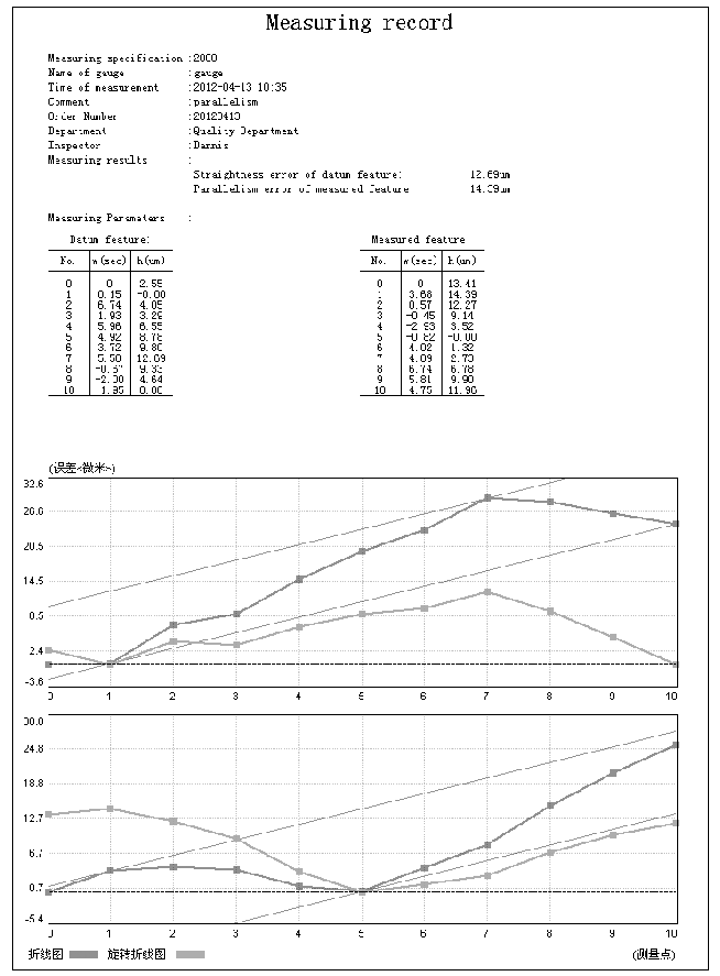
Fig6: Report